Detailed curriculum modules
Explore the supplied arm firmware development learning sequence.


ARM FIRMWARE DEVELOPMENT / ENGINEERING LEARNING
Understand the peripherals behind dependable firmware.
Suggested duration: 90 hours.
Develop ARM Cortex-M firmware with STM32 architecture, register-level Embedded C, STM32CubeIDE, HAL and LL libraries, GPIO, timers, interrupts, analog acquisition, serial and CAN communication, DMA and FreeRTOS. Apply debugging and PCB development concepts through seven practical projects and a final technical demonstration.
Starting level, batch dates, software and equipment are confirmed through counselling. See fees and batch timings below. An enquiry is not a confirmed booking.

PLAN AHEAD
Course fee / 90 hours₹19,999 + 18% tax
Total including tax₹23,598.82
Regular, weekend and Sunday batches available. Monday–Saturday: preferred slots 9am–6pm; Sunday: 10am–1pm (IST). Slots, dates and places require availability confirmation.
Fees exclude 18% tax; totals include tax. Confirm material, licence and take-home kit charges before enrolment. Enquiry is not a reservation.
ARM MICROCONTROLLER & STM32 DEVELOPMENT / AT A GLANCE
Explore the supplied arm firmware development learning sequence.
Session frequency and calendar duration are confirmed by enquiry.
Seven applications share the seven hours allocated to Module 11.
01 / COURSE PERSPECTIVE
Suggested preparation: embedded C, GPIO, timers and basic serial communication.
Discuss preparation and readiness with a mentor before choosing a batch. These are recommended starting points, not a guarantee of placement.
Explain Cortex-M architecture, write register-level Embedded C and HAL/LL firmware, configure STM32 peripherals, acquire sensor data, implement serial and CAN communication, use DMA and FreeRTOS, debug hardware and firmware, and demonstrate seven embedded applications.
Project scope depends on supervision, equipment and practice. Examples describe learning activities, not verified student work or guaranteed outcomes.
02 / WHAT YOU WILL WORK ON
Connect Cortex-M concepts with STM32 memory, GPIO and peripheral configuration.
Explore interrupts, NVIC, timers, ADC, DMA, serial and CAN communication, and FreeRTOS without assuming every board has identical peripherals.
Use register-level C, HAL/LL and CMSIS, then inspect breakpoints, registers and test evidence alongside PCB prototyping concepts.
03 / CURRICULUM & PRACTICE
Twelve modules total 90 hours. Seven one-hour projects are included in Module 11; the final three hours cover assessment and demonstration. Check the selected STM32 family and board: cores, DAC, CAN/CAN FD, USB, cache and other peripherals vary. Required transceivers and voltage levels must be verified.
04 / INDUSTRIAL EMBEDDED PROJECTS & APPLICATIONS
Each application has one hour inside Module 11, not additional course hours. Use isolated training hardware, supervised low-voltage circuits or simulation. These conceptual illustrations are not wiring instructions, validated industrial controllers or verified student builds.
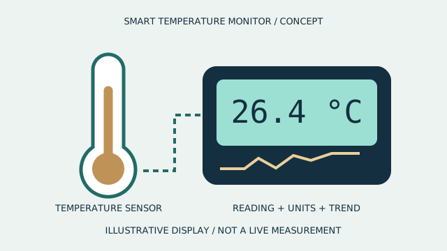
PROJECT 1 / 1 PRACTICAL HOUR
Acquire temperature measurements on an isolated educational STM32 setup.
Evidence to discuss: Record units, calibration assumptions and responses to missing or out-of-range readings.

PROJECT 2 / 1 PRACTICAL HOUR
Generate bounded PWM commands for a supervised low-voltage motor or simulation.
Evidence to discuss: Compare commanded duty cycle with observed response and check driver limits.
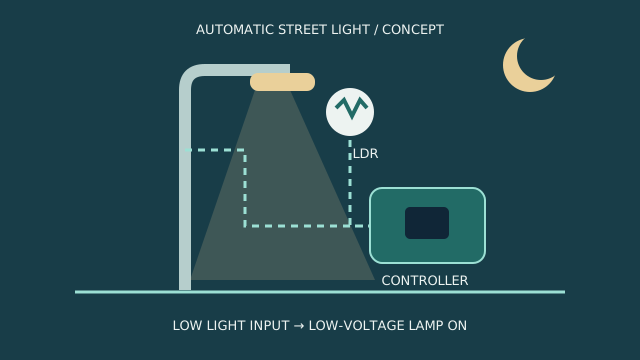
PROJECT 3 / 1 PRACTICAL HOUR
Connect a validated sensor reading to a protected low-voltage output.
Evidence to discuss: Test thresholds, boundary cases and predictable behavior when input is unavailable.

PROJECT 4 / 1 PRACTICAL HOUR
Connect multiple test devices through supported STM32 serial interfaces.
Evidence to discuss: Document addressing, frame exchange and communication fault diagnostics.

PROJECT 5 / 1 PRACTICAL HOUR
Exchange sample CAN messages on an isolated training bus or simulation.
Evidence to discuss: Explain message filtering and observed error conditions; use appropriate transceivers and termination.
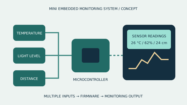
PROJECT 6 / 1 PRACTICAL HOUR
Coordinate acquisition and monitoring tasks using FreeRTOS queues and synchronization.
Evidence to discuss: Present task timing, resource sharing and stack/heap observations.
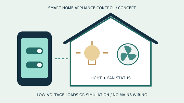
PROJECT 7 / 1 PRACTICAL HOUR
Integrate sensing, firmware decisions and supervised low-voltage outputs into a controller prototype.
Evidence to discuss: Demonstrate normal and interrupted input cases and document a troubleshooting revision.
ARM FIRMWARE DEVELOPMENT / PROJECT WORKFLOW
Scroll to follow the journey. On a smaller screen, swipe the cards or use your keyboard.
Check the selected STM32 device and assign the required interfaces.
Explain generated configuration and verify the relevant registers or runtime values.
Test interrupt and data-transfer behavior before adding control logic.
Use debugger evidence to explain a multi-sensor system's behavior.
ARM FIRMWARE DEVELOPMENT / INTERACTIVE CONCEPT
Inspect a conceptual microcontroller board, peripheral interface and connection layer. Use it to discuss configuration and data paths; it is not an STM32 pinout or register map.
This illustrative 3D model is not a hardware specification, a functional simulation, a fabrication file or equipment promised with enrolment.
Inspect a conceptual microcontroller board, peripheral interface and connection layer. Use it to discuss configuration and data paths; it is not an STM32 pinout or register map. Interactive rotation and layer separation require JavaScript and WebGL.
Drag to rotate. On desktop, scroll to separate the layers, or use the controls.
05 / TOOLS & RESPONSIBLE PRACTICE
Suggested setup: an appropriate STM32 development board, STM32CubeIDE/CubeMX, HAL/LL and CMSIS, ST-LINK, FreeRTOS, sensors, displays, protected low-voltage motor drivers, serial/CAN interfaces and KiCad. Logic analyzer, oscilloscope and fabrication access depend on supervised facilities; check the specific board and toolchain capabilities.
Confirm hardware, software versions, licences, consumables, fabrication and lab access before enrolment. No personal kit or software licence is promised.
Confirm board voltage levels, alternate functions, debugger connections and family-specific DAC, CAN/CAN FD, USB and cache availability. Use suitable interface transceivers and supervised low-voltage circuits or simulation; GPIO pins do not tolerate every sensor supply. No mains wiring, live industrial bus or production machine connections are authorized.
06 / BEFORE YOU JOIN
Develop ARM Cortex-M firmware with STM32 architecture, register-level Embedded C, STM32CubeIDE, HAL and LL libraries, GPIO, timers, interrupts, analog acquisition, serial and CAN communication, DMA and FreeRTOS. Apply debugging and PCB development concepts through seven practical projects and a final technical demonstration.
Suggested preparation: embedded C, GPIO, timers and basic serial communication.
Explain Cortex-M architecture, write register-level Embedded C and HAL/LL firmware, configure STM32 peripherals, acquire sensor data, implement serial and CAN communication, use DMA and FreeRTOS, debug hardware and firmware, and demonstrate seven embedded applications. The application studio shows selected briefs or stages.
The suggested curriculum is 90 hours. Confirm session frequency, batch dates and any independent practice time before booking.
Suggested setup: an appropriate STM32 development board, STM32CubeIDE/CubeMX, HAL/LL and CMSIS, ST-LINK, FreeRTOS, sensors, displays, protected low-voltage motor drivers, serial/CAN interfaces and KiCad. Logic analyzer, oscilloscope and fabrication access depend on supervised facilities; check the specific board and toolchain capabilities. Equipment, licences, fees, delivery mode and lab access must be confirmed for each batch.
Request counselling to confirm prerequisites, course availability and scheduling. An enquiry is not a confirmed booking.
START WITH A COURSE CONVERSATION
Share your current experience and project goals. Confirm readiness, availability, fees, tools and class arrangements with TECHNOVA.
THE COURSE JOURNAL
Understand STM32 peripheral configuration through clocks, timers, interrupts and debugging evidence, rather than treating generated firmware as a black box.
Read the course article